Monge Technical Drawing Elevation Plan
Multiview orthographic projection
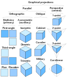
Last updatedIn technical drawing and calculator graphics, a multiview projection is a technique of illustration by which a standardized series of orthographic ii-dimensional pictures are synthetic to represent the form of a iii-dimensional object. Up to six pictures of an object are produced (called primary views), with each project aeroplane parallel to 1 of the coordinate axes of the object. The views are positioned relative to each other according to either of two schemes: first-angle or third-angle projection. In each, the appearances of views may be idea of as being projected onto planes that form a six-sided box effectually the object. Although six dissimilar sides can be drawn, usually 3 views of a cartoon give enough information to brand a three-dimensional object. These views are known as front view, top view and end view. Other names for these views include program, elevation and section. When the plane or axis of the object depicted is not parallel to the projection plane, and where multiple sides of an object are visible in the aforementioned image, information technology is called an auxiliary view.
- Overview
- Chief views
- Plan
- Elevation
- Section
- Auxiliary views
- Multiviews
- Quadrants in descriptive geometry
- First-angle project
- 3rd-bending projection
- Additional data
- Symbol
- Multiviews without rotation
- Territorial utilize
- Come across also
- References
- External links
Overview

To render each such picture, a ray of sight (also chosen a project line, project ray or line of sight) towards the object is chosen, which determines on the object various points of interest (for example, the points that are visible when looking at the object along the ray of sight); those points of interest are mapped past an orthographic project to points on some geometric airplane (chosen a projection plane or paradigm airplane ) that is perpendicular to the ray of sight, thereby creating a 2nd representation of the 3D object.
Customarily, two rays of sight are chosen for each of the 3 axes of the object'due south coordinate system; that is, parallel to each axis, the object may be viewed in i of 2 contrary directions, making for a total of vi orthographic projections (or "views") of the object: [1]
- Forth a vertical axis (often the y-centrality): The top and bottom views, which are known as plans (because they show the arrangement of features on a horizontal airplane, such as a floor in a building).
- Along a horizontal centrality (often the z-centrality): The front and dorsum views, which are known as elevations (because they show the heights of features of an object such as a building).
- Forth an orthogonal axis (oftentimes the x-axis): The left and right views, which are also known as elevations, following the same reasoning.
These six planes of projection intersect each other, forming a box around the object, the most uniform structure of which is a cube; traditionally, these six views are presented together by offset projecting the 3D object onto the 2D faces of a cube, and then "unfolding" the faces of the cube such that all of them are contained within the same airplane (namely, the airplane of the medium on which all of the images volition be presented together, such as a slice of newspaper, or a reckoner monitor, etc.). Yet, even if the faces of the box are unfolded in i standardized fashion, there is ambiguity as to which project is being displayed by a particular face; the cube has 2 faces that are perpendicular to a ray of sight, and the points of interest may be projected onto either one of them, a choice which has resulted in two predominant standards of projection:
- Outset-angle projection: In this blazon of projection, the object is imagined to be in the get-go quadrant. Because the observer ordinarily looks from the correct side of the quadrant to obtain the front view, the objects will come up in between the observer and the airplane of project. Therefore, in this case, the object is imagined to exist transparent, and the projectors are imagined to be extended from various points of the object to meet the projection plane. When these meeting points are joined in club on the plane they form an epitome, thus in the kickoff bending projection, any view is and so placed that it represents the side of the object away from it. First angle project is oftentimes used throughout parts of Europe so that it is often called European project.
- Tertiary-angle project: In this type of projection, the object is imagined to be in the 3rd quadrant. Over again, equally the observer is normally supposed to expect from the correct side of the quadrant to obtain the forepart view, in this method, the projection plane comes in between the observer and the object. Therefore, the plane of projection is assumed to be transparent. The intersection of this plan with the projectors from all the points of the object would form an paradigm on the transparent airplane.
Chief views
Multiview projections testify the primary views of an object, each viewed in a management parallel to one of the master coordinate axes. These primary views are called plans and elevations. Sometimes they are shown as if the object has been cut beyond or sectioned to expose the interior: these views are called sections.
Plan

A plan is a view of a three-dimensional object seen from vertically above (or sometimes below [ citation needed ] ). Information technology may be drawn in the position of a horizontal plane passing through, above, or below the object. The outline of a shape in this view is sometimes called its planform, for example with aircraft wings.
The program view from in a higher place a building is called its roof plan. A section seen in a horizontal aeroplane through the walls and showing the flooring beneath is chosen a floor plan.
Elevation

Elevation is the view of a 3-dimensional object from the position of a vertical plane beside an object. In other words, an elevation is a side view as viewed from the front, back, left or correct (and referred to as a front elevation, [left/ right] side elevation, and a rear tiptop).
An summit is a mutual method of depicting the external configuration and detailing of a three-dimensional object in two dimensions. Edifice façades are shown as elevations in architectural drawings and technical drawings.
Elevations are the most common orthographic projection for carrying the appearance of a building from the exterior. Perspectives are also commonly used for this purpose. A building elevation is typically labeled in relation to the compass direction it faces; the direction from which a person views it. E.g. the N Top of a edifice is the side that near closely faces true north on the compass. [2]
Interior elevations are used to show details such as millwork and trim configurations.
In the building manufacture elevations are non-perspective views of the structure. These are drawn to scale and then that measurements can exist taken for whatsoever aspect necessary. Drawing sets include front end, rear, and both side elevations. The elevations specify the limerick of the unlike facades of the building, including ridge heights, the positioning of the concluding autumn of the land, exterior finishes, roof pitches, and other architectural details.
Adult elevation
A developed elevation is a variant of a regular elevation view in which several adjacent non-parallel sides may be shown together as if they have been unfolded. For instance, the north and west views may be shown side-past-side, sharing an edge, even though this does not stand for a proper orthographic project.
Department
A section, or cantankerous-section, is a view of a 3-dimensional object from the position of a airplane through the object.
A section is a mutual method of depicting the internal system of a 3-dimensional object in ii dimensions. It is ofttimes used in technical drawing and is traditionally crosshatched. The way of crosshatching often indicates the type of material the section passes through.
With computed axial tomography, computers construct cantankerous-sections from ten-ray data.
-

A three-D view of a beverage-can stove with a cross-section in yellow.
-

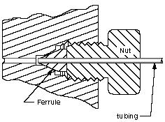
A 2-D cantankerous-sectional view of a pinch seal.
-

-
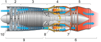
Cross-department of a jet engine
Auxiliary views
An auxiliary view or pictorial, is an orthographic view that is projected into any plane other than one of the half dozen primary views. [3] These views are typically used when an object has a surface in an oblique airplane. By projecting into a plane parallel with the oblique surface, the truthful size and shape of the surface are shown. Auxiliary views are oft fatigued using isometric project.
Multiviews
Quadrants in descriptive geometry

Modern orthographic projection is derived from Gaspard Monge's descriptive geometry. [4] Monge defined a reference arrangement of 2 viewing planes, horizontal H ("basis") and vertical V ("backdrop"). These two planes intersect to partition 3D space into iv quadrants, which he labeled:
- I: above H, in front of V
- Two: above H, behind V
- III: below H, backside Five
- IV: below H, in forepart of V
These quadrant labels are the same every bit used in 2d planar geometry, as seen from infinitely far to the "left", taking H and V to be the X-axis and Y-axis, respectively.
The 3D object of involvement is and so placed into either quadrant I or 3 (equivalently, the position of the intersection line between the two planes is shifted), obtaining beginning- and third-angle projections, respectively. Quadrants Two and IV are also mathematically valid, just their use would result in 1 view "true" and the other view "flipped" past 180° through its vertical centerline, which is as well confusing for technical drawings. (In cases where such a view is useful, e.g. a ceiling viewed from to a higher place, a reflected view is used, which is a mirror prototype of the truthful orthographic view.)
Monge'due south original formulation uses two planes only and obtains the peak and front views only. The addition of a third airplane to evidence a side view (either left or correct) is a modern extension. The terminology of quadrant is a mild anachronism, as a mod orthographic projection with 3 views corresponds more precisely to an octant of 3D space.
First-angle project
In first-bending projection, the object is conceptually located in quadrant I, i.e. it floats above and earlier the viewing planes, the planes are opaque, and each view is pushed through the object onto the plane furthest from it. (Mnemonic: an "actor on a stage".) Extending to the half dozen-sided box, each view of the object is projected in the direction (sense) of sight of the object, onto the (opaque) interior walls of the box; that is, each view of the object is fatigued on the opposite side of the box. A two-dimensional representation of the object is so created by "unfolding" the box, to view all of the interior walls. This produces two plans and iv elevations. A simpler way to visualize this is to place the object on superlative of an upside-down basin. Sliding the object downwards the right edge of the bowl reveals the correct side view.
-

An prototype of an object in a box.
-

The same image, with views of the object projected in the direction of sight onto walls using first-bending project.
-

Similar image showing the box unfolding from around the object.
-

Image showing orthographic views located relative to each other in accordance with kickoff-angle projection.
Third-angle projection

In third-angle projection, the object is conceptually located in quadrant III, i.eastward. it is positioned below and behind the viewing planes, the planes are transparent, and each view is pulled onto the airplane closest to it. (Mnemonic: a "shark in a tank", esp. that is sunken into the flooring.) Using the half dozen-sided viewing box, each view of the object is projected opposite to the management (sense) of sight, onto the (transparent) exterior walls of the box; that is, each view of the object is drawn on the aforementioned side of the box. The box is then unfolded to view all of its exterior walls. A simpler way to visualize this is to place the object in the bottom of a bowl. Sliding the object up the correct edge of the bowl reveals the right side view.
Here is the construction of third angle projections of the same object as above. Note that the individual views are the same, just bundled differently.


Additional information

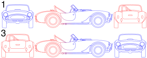
Get-go-bending projection is as if the object were sitting on the paper and, from the "face" (front) view, it is rolled to the right to show the left side or rolled upwardly to bear witness its bottom. It is standard throughout Europe and Asia (excluding Japan). Beginning-angle projection was widely used in the U.k., but during World War Ii, British drawings sent to exist manufactured in the USA, such every bit of the Rolls-Royce Merlin, had to exist drawn in third-bending projection before they could be produced, e.g., every bit the Packard V-1650 Merlin. This meant that some British companies completely adopted 3rd bending projection. BS 308 (Role one) Applied science Drawing Practice, gave the choice of using both projections, just generally, every illustration (other than the ones explaining the departure between first and third-angle) was done in first-angle. After the withdrawal of BS 308 in 1999, BS 8888 offered the aforementioned choice since it referred directly to ISO 5456-2, Technical drawings – Project methods – Function two: Orthographic representations.
Tertiary-angle is every bit if the object were a box to be unfolded. If we unfold the box so that the front view is in the center of the 2 artillery, so the tiptop view is above it, the bottom view is below it, the left view is to the left, and the correct view is to the right. It is standard in the USA (ASME Y14.iii-2003 specifies it as the default projection arrangement), Nippon (JIS B 0001:2010 specifies information technology as the default project system), Canada, and Australia.
Both first-angle and third-bending projections result in the same 6 views; the difference between them is the arrangement of these views effectually the box.
Symbol

A great bargain of confusion has ensued in drafting rooms and technology departments when drawings are transferred from i convention to another. On engineering drawings, the project is denoted by an international symbol representing a truncated cone in either first-angle or third-angle project, as shown by the diagram on the right.
The 3D interpretation is a solid truncated cone, with the pocket-sized end pointing toward the viewer. The front view is, therefore, two concentric circles. The fact that the inner circle is drawn with a solid line instead of dashed identifies this view equally the front view, not the rear view. The side view is an isosceles trapezoid.
- In start-angle projection, the front end view is pushed back to the rear wall, and the right side view is pushed to the left wall, so the first-angle symbol shows the trapezoid with its shortest side away from the circles.
- In 3rd-angle project, the front view is pulled forrard to the front end wall, and the correct side view is pulled to the right wall, so the 3rd-angle symbol shows the trapezoid with its shortest side towards the circles.
Multiviews without rotation
Orthographic multiview projection is derived from the principles of descriptive geometry and may produce an image of a specified, imaginary object as viewed from any direction of space. Orthographic projection is distinguished by parallel projectors emanating from all points of the imaged object and which intersect of project at right angles. Above, a technique is described that obtains varying views past projecting images afterwards the object is rotated to the desired position.
Descriptive geometry customarily relies on obtaining various views past imagining an object to be stationary and changing the management of projection (viewing) in society to obtain the desired view.
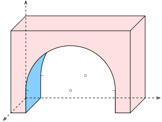
See Figure 1. Using the rotation technique above, note that no orthographic view is bachelor looking perpendicularly at any of the inclined surfaces. Suppose a technician desired such a view to, say, wait through a hole to be drilled perpendicularly to the surface. Such a view might be desired for calculating clearances or for dimensioning purposes. To obtain this view without multiple rotations requires the principles of Descriptive Geometry. The steps below describe the apply of these principles in tertiary angle project.

- Fig.one: Pictorial of the imaginary object that the technician wishes to paradigm.
- Fig.2: The object is imagined behind a vertical plane of projection. The angled corner of the plane of projection is addressed later.
- Fig.3: Projectors emanate parallel from all points of the object, perpendicular to the plane of project.
- Fig.four: An epitome is created thereby.
- Fig.5: A second, horizontal airplane of projection is added, perpendicular to the offset.
- Fig.vi: Projectors emanate parallel from all points of the object perpendicular to the second plane of projection.
- Fig.vii: An image is created thereby.
- Fig.viii: The third plane of projection is added, perpendicular to the previous two.
- Fig.9: Projectors emanate parallel from all points of the object perpendicular to the third plane of projection.

- Fig.ten: An image is created thereby.
- Fig.eleven: The fourth aeroplane of projection is added parallel to the called inclined surface, and perforce, perpendicular to the first (Frontal) plane of projection.
- Fig.12: Projectors emanate parallel from all points of the object perpendicularly from the inclined surface, and perforce, perpendicular to the fourth (Auxiliary) aeroplane of projection.
- Fig.thirteen: An paradigm is created thereby.
- Fig.fourteen-xvi: The various planes of projection are unfolded to be planar with the Frontal plane of projection.
- Fig.17: The final advent of an orthographic multiview projection and which includes an "Auxiliary view" showing the true shape of an inclined surface.
Territorial employ
First-angle is used in near of the world. [5]
Third-bending projection is most unremarkably used in America, [6] Japan (in JIS B 0001:2010); [seven] and is preferred in Australia, as laid downwards in AS 1100.101—1992 6.3.3. [eight]
In the UK, BS8888 nine.seven.2.ane allows for 3 unlike conventions for arranging views: Labelled Views, Third Bending Project, and Starting time Angle Projection.
Run into also
- Architectural drawing
- Cross section (geometry)
- Engineering drawing
- Graphical projection
- Plans (drawings)
Related Research Articles

Technical drawing, drafting or cartoon, is the act and discipline of composing drawings that visually communicate how something functions or is constructed.

In elementary geometry, ii geometric objects are perpendicular if they intersect at a correct angle.

A mirror image is a reflected duplication of an object that appears most identical, just is reversed in the direction perpendicular to the mirror surface. Every bit an optical event information technology results from reflection off from substances such as a mirror or water. It is too a concept in geometry and can be used as a conceptualization process for 3-D structures.

Isometric project is a method for visually representing three-dimensional objects in two dimensions in technical and engineering science drawings. Information technology is an axonometric projection in which the three coordinate axes appear equally foreshortened and the angle between any 2 of them is 120 degrees.

An applied science drawing is a type of technical drawing that is used to convey information most an object. A mutual employ is to specify the geometry necessary for the construction of a component and is chosen a detail cartoon. Normally, a number of drawings are necessary to completely specify even a simple component. The drawings are linked together by a chief drawing or associates cartoon which gives the drawing numbers of the subsequent detailed components, quantities required, construction materials and perchance 3D images that tin be used to locate individual items. Although mostly consisting of pictographic representations, abbreviations and symbols are used for brevity and additional textual explanations may also be provided to convey the necessary data.
Orthographic projection is a means of representing three-dimensional objects in 2 dimensions. Information technology is a form of parallel projection, in which all the projection lines are orthogonal to the projection plane, resulting in every plane of the scene actualization in affine transformation on the viewing surface. The obverse of an orthographic projection is an oblique projection, which is a parallel projection in which the projection lines are not orthogonal to the projection airplane.

A 3D project is a design technique used to display a three-dimensional (3D) object on a ii-dimensional (2nd) surface. These projections rely on visual perspective and aspect analysis to project a complex object for viewing adequacy on a simpler airplane. This concept of extending 2d geometry to 3D was mastered by Heron of Alexandria in the first century. Heron could be called the father of 3D. 3D Projection is the basis of the concept for Estimator Graphics simulating fluid flows to imitate realistic effects. Lucas Films 'ILM group is credited with introducing the concept.
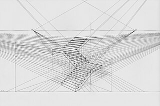
Linear or betoken-project perspective is one of two types of graphical project perspective in the graphic arts; the other is parallel projection. Linear perspective is an approximate representation, generally on a apartment surface, of an image as information technology is seen past the middle. The about characteristic features of linear perspective are that objects announced smaller as their distance from the observer increases, and that they are subject to foreshortening, pregnant that an object's dimensions forth the line of sight appear shorter than its dimensions beyond the line of sight. All objects volition recede to points in the distance, ordinarily along the horizon line, just too higher up and below the horizon line depending on the view used.
Axonometric project is a type of orthographic projection used for creating a pictorial drawing of an object, where the object is rotated around one or more of its axes to reveal multiple sides.

Descriptive geometry is the branch of geometry which allows the representation of three-dimensional objects in ii dimensions by using a specific set of procedures. The resulting techniques are important for engineering, architecture, blueprint and in fine art. The theoretical ground for descriptive geometry is provided past planar geometric projections. The earliest known publication on the technique was "Underweysung der Messung mit dem Zirckel und Richtscheyt", published in Linien, Nuremberg: 1525, by Albrecht Dürer. Italian architect Guarino Guarini was as well a pioneer of projective and descriptive geometry, as is clear from hisPlacita Philosophica (1665), Euclides Adauctus (1671) and Architettura Civile, anticipating the work of Gaspard Monge (1746–1818), who is unremarkably credited with the invention of descriptive geometry. Gaspard Monge is usually considered the "father of descriptive geometry" due to his developments in geometric trouble solving. His first discoveries were in 1765 while he was working as a draftsman for military fortifications, although his findings were published later on.
Oblique projection is a simple type of technical drawing of graphical projection used for producing two-dimensional (2d) images of 3-dimensional (3D) objects.

A vanishing point is a betoken on the epitome plane of a perspective drawing where the two-dimensional perspective projections of mutually parallel lines in 3-dimensional space announced to converge. When the set of parallel lines is perpendicular to a pic airplane, the structure is known as one-indicate perspective, and their vanishing point corresponds to the oculus, or "middle point", from which the image should be viewed for correct perspective geometry. Traditional linear drawings use objects with ane to 3 sets of parallels, defining 1 to three vanishing points.
In painting, photography, graphical perspective and descriptive geometry, a picture plane is an prototype plane located between the "eye signal" and the object being viewed and is usually coextensive to the material surface of the work. Information technology is ordinarily a vertical airplane perpendicular to the sightline to the object of interest.
In geometry and science, a cross section is the non-empty intersection of a solid torso in iii-dimensional infinite with a plane, or the analog in higher-dimensional spaces. Cutting an object into slices creates many parallel cross-sections. The purlieus of a cross-section in iii-dimensional space that is parallel to two of the axes, that is, parallel to the plane adamant by these axes, is sometimes referred to as a contour line; for instance, if a airplane cuts through mountains of a raised-relief map parallel to the footing, the result is a profile line in two-dimensional space showing points on the surface of the mountains of equal elevation.
A parallel projection is a projection of an object in 3-dimensional space onto a fixed plane, known equally the project plane or image plane, where the rays, known as lines of sight or projection lines, are parallel to each other. It is a bones tool in descriptive geometry. The projection is called orthographic if the rays are perpendicular (orthogonal) to the image airplane, and oblique or skew if they are not.
In Gaussian optics, the primal points consist of 3 pairs of points located on the optical axis of a rotationally symmetric, focal, optical system. These are the focal points, the principal points, and the nodal points. For ideal systems, the basic imaging properties such equally prototype size, location, and orientation are completely determined by the locations of the fundamental points; in fact merely four points are necessary: the focal points and either the principal or nodal points. The only platonic organization that has been achieved in practice is the airplane mirror, withal the central points are widely used to guess the beliefs of real optical systems. Fundamental points provide a mode to analytically simplify a arrangement with many components, allowing the imaging characteristics of the arrangement to exist approximately determined with simple calculations.

Plans are a set of drawings or two-dimensional diagrams used to describe a place or object, or to communicate edifice or fabrication instructions. Ordinarily plans are drawn or printed on paper, only they can take the form of a digital file.
Planar projections are the subset of 3D graphical projections constructed by linearly mapping points in three-dimensional infinite to points on a two-dimensional projection plane. The projected bespeak on the aeroplane is chosen such that it is collinear with the corresponding three-dimensional bespeak and the centre of projection. The lines connecting these points are commonly referred to as projectors.

The sine quadrant was a blazon of quadrant used by medieval Arabic astronomers. Information technology is also known as a "sinecal quadrant" in the English-speaking world. The instrument could be used to measure angelic angles, to tell time, to detect directions, or to decide the apparent positions of any celestial object for any time. The proper noun is derived from the Arabic rub meaning 'a quarter' and mujayyab meaning 'marked with sine'. It was described, according to Rex, by Muhammad ibn Mūsā al-Khwārizmī in 9th century Baghdad.
Axonometry is a graphical process belonging to descriptive geometry that generates a planar image of a three-dimensional object. The term "axonometry" means "to measure along axes", and indicates that the dimensions and scaling of the coordinate axes play a crucial part. The issue of an axonometric procedure is a uniformly-scaled parallel projection of the object. In full general, the resulting parallel projection is oblique ; but in special cases the issue is orthographic, which in this context is chosen an orthogonal axonometry.
References
- ↑ Ingrid Carlbom, Joseph Paciorek (1978), "Planar Geometric Projections and Viewing Transformations", ACM Computing Surveys , ten (4): 465–502, CiteSeerX x.1.1.532.4774 , doi:10.1145/356744.356750, S2CID 708008
- ↑ Ching, Frank (1985), Architectural Graphics - Second Edition, New York: Van Norstrand Reinhold, ISBN 978-0-442-21862-1
- ↑ Bertoline, Gary R. Introduction to Graphics Communications for Engineers (4th Ed.). New York, NY. 2009
- ↑ "Geometric Models - Jullien Models for Descriptive Geometry". Smithsonian Institution . Retrieved 2019-12-11 .
- ↑ "Third Angle Projection". Archived from the original on March 4, 2016. Retrieved December 10, 2019.
- ↑ Madsen, David A.; Madsen, David P. (1 February 2016). Technology Drawing and Design. Cengage Learning. ISBN 9781305659728 – via Google Books.
- ↑ "Third Bending Projection". Musashino Art University . Retrieved vii Dec 2016.
- ↑ "Total text of "AS 1100.101 1992 Technical Dwgs"". archive.org.
BS 308 (Part 1) Engineering Cartoon Practice BS 8888 Technical production documentation and specification ISO 5456-two Technical drawings – Projection methods – Part 2: Orthographic Representations (includes the truncated cone symbol)
External links
- Educational website describing the principles of first and tertiary angle projection — University of Limerick
- Educational website describing the principles of start and 3rd angle projection
- Images tagged "Superlative" on Flickr.com
- Basic Projection Method offset bending vs the third angle
This page is based on this Wikipedia commodity
Text is bachelor nether the CC By-SA 4.0 license; additional terms may apply.
Images, videos and audio are available under their respective licenses.
Source: https://wikimili.com/en/Multiview_orthographic_projection
0 Response to "Monge Technical Drawing Elevation Plan"
Post a Comment